Field and Laboratory Tests in Rock Mechanics by L. G. Alexander

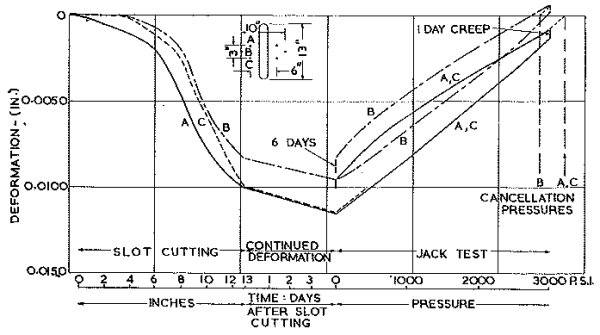
Fig. 9.— Flat Jack Test Curve.
It is possible to use the jacks for the measurement of very high stresses. For example, in the abutment corners of Tumut 2 machine hall excavation, typical results are:
| Slot Contraction | Stress | Site Modulus | Rock Condition |
|---|---|---|---|
| 0.02in. | 7,000 p.s.i. | 12 × 106 p.s.i. | Few joints |
| 0.05 in. | 8,500 p.s.i. | 5 × 10⁶ p.s.i. | Complex close-jointed structure |
The jack pressures attainable are high enough, in some cases, for an in-situ test of rock strength, e.g.
| Max. jack Pressure | Rock Failure |
|---|---|
| 9,200 p.s.i. | 4 in. deep × 12 × 9 in. piece dislodged. |
Rock failure, however, frequently occurs at lower pressures.
As a set of typical measured stresses, the results from the exploratory tunnel for the geological investigation of the Tumut 2 Power Station site may be given. This Tunnel is driven at a depth of 610-650 ft. (measured directly to the surface), but, owing to a local depression, the average overburden is estimated somewhat higher, at 700 ft. The rock types along the 180-ft. length where twelve sites were tested were granitic gneiss and biotite granite, but there appears to be no correlation of rock type with the values of stress or of site modulus.
Measured Stresses—p.s.i.
| Vertical in walls V |
Horizontal, in roof at right angles to tunnel direction T |
Horizontal, in walls, along tunnel direction L |
|---|---|---|
| 2,250 | 2,150 | 2,150 |
| 600 | 3,600 | 1,700 |
| 1,350 | 700 | 700 |
| 2,600 | 3,300 | 1,050 |
From these results it is desired to arrive at estimates of the primary rock stresses, assumed uniform in the rock mass undisturbed by the presence of the tunnel. These primary stresses are required as data for the study of the stress distribution around a proposed power station excavation in the area, by means of photoelastic and analogue tests.
Evaluation of Primary Stresses and Relation to Topography:
On the elastic theory, stress concentration occurs around an opening (in a uniform isotropic medium) according to equations (Worotnicki, S.M.A. internal report) of the type:
V = fv + gt
T = f´t + g´v
L = kl + μ( f − 1 ) v + μ( g − 1 ) t,
where
v, t, l =
the normal primary rock stresses in the directions corresponding to V, T, L.
f,f´,g,g´ =
stress concentration factors (which may be determined by the photoelastic method on a model of the tunnel cross-section).
k =
a stress concentration factor, close to unity, which depends on the irregularity of the longitudinal section through the site.
