UNSTABLE ROCK AND ITS TREATMENT SNOWY MOUNTAINS SCHEME

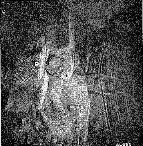
Fig. 5.---Granite, loosely jointed with many seams of clay and partly decomposed rock. Supported by steel sets, rock bolts and mesh. The whole area was concrete lined.
The inflexible requirement that the steel ribs must be on line and grade, irrespective of details of the shape and condition of the surrounding rock, considerably limits their convenience and to some extent also their value as support. The bases of the ribs are set on footings made of timber blocks. The ribs are firmly blocked with timber blocks and wedges against the rock surface, particularly at the springline, shoulders and crown. This must be done systematically and with considerable care since it is the principal means of developing an active contact between the steel rib and the rock whereby the steel rib can carry rock load (Proctor and White, 1946, p. 107). Timber cribbing spanning between ribs is built up to the roof and serves as the main protective canopy against fallout of rock between blocking points (Fig. 5). Installation of timber cribbing is restricted by the design requirement to obtain a concrete lining which will bear directly against rock over a large proportion of any cross-sectional area, for the full thickness of the concrete, measured radially, without the intervention of timber. This minimizes the transference of rock load to concrete through timber.
Rock bolts
Rock bolts were first used on a large scale in the Snowy Mountains during the construction of Tumut 1 Underground Power Station, excavated in 1956-57. Since then they have been used extensively underground, both for temporary support during construction and as a primary means of permanent support.
The bolting practice now in use has evolved from experimental investigations and experience during the routine use of rock bolts (Lang, 1957, 1959; Moye, 1959; Leech and Pender, 1961; Pender, Hosking and Mattner, 1963).
In the recently excavated (1962-64) Snowy-Eucumbene, Snowy-Geehi and Murray 1 Tunnels, which range in excavated diameter from 22 to 24 ft and have a total length of about 32 miles, the rock bolts used have the following characteristics. They are mostly 8 ft long (some are 10 ft) steel bars, one inch in nominal diameter, made of a plain mild steel. They are fitted at one end with an expansion shell anchor. The other end is threaded with a rolled thread 5½ in. long, and is fitted with a flat steel bearing plate 6 in. by 6 in. by ⅜ in., taper and machine washers, and a hexagon nut. Bolts which are required to be grouted have deformed shanks, and a hollow core for de-aeration (Fig. 6).
These bolts are firmly anchored and stressed by rotation of the nut against the bearing plate assembly by means of an impact wrench. A torque of 250 lb/ft is used, giving under average conditions a tensile force of about 15,500 lb in the bolt. The load which can be put on a bolt during installation is limited by the shear stress due to torsion which can cause yielding of the bolts at tensions much below its capacity in pure tension. The yield load for these bolts is about 33,000 lb and the ultimate load about 40,000 lb. Considerable elongation occurs bctween yield and failure.
