Rock mechanics in the investigation and construction of Tumut 1 Underground Power Station, Snowy Mountains, Australia
In the experimental investigations described by T. A, Lang (1957), many bolts in groups were used on a variety of materials including regularly shaped plastic blocks, angular particles of crushed rock ranging from 3/16 inch to 5 inches in diameter, and plastic rods. These showed that for certain spacings and lengths of bolts the effects of indiviual bolts interacted, and the original loose mass of particles could be reconstituted into an integral structure capable of carrying considerable loads, and which behaved quasi-elastically.
For angular particles of crushed rock it was found that if the ratio of the free space between bolts to the diameter of the particles was less than about 7, particles fell out between bolts, but eventually a stable vault was formed. If this ratio was greater than 7, fall-out continued, and the mass collapsed, The ratio of length of bolts to spacing of bolts required for stability was found to be 2 or greater.
Use of Rock Bolts in the Power Station
lt was considered that rock bolts, properly used, possessed considerable advantages over conventional steel supports. Also, they frequently possess other engineering advantages which will not be discussed here.
Consequently, rock bolts were used extensively for support in the roof and walls of the machine hall and transformer hall, and in other openings, These bolts consisted of mild steel bars l inch in diameter, mostly 10 or 15 feet long, with a slot-and-wedge type anchor and furnished with 6-inch or 8-inch square steel plates for bearing against the rock surface. During installation they were stressed to a nominal load of 20, 000 pounds tension.
The bolting in the power-station excavations was carried out systematically to a pattern. Bolts were usually 10 or 15 feet long and spaced 4 or 5 feet apart, so the ratio of length to spacing ranged from 2 to 3.
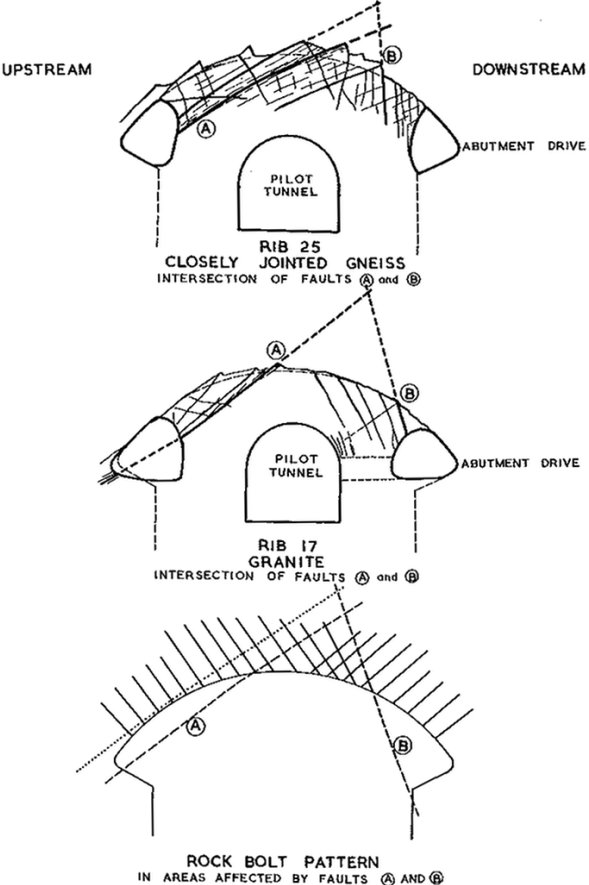
Within this pattern the location of individual bolts could be varied slightly to take account of the jointing in the surface layer of rock; bolts were placed toward the center of joint blocks rather than on their edges. Where there were well-defined persistent joints or minor faults the pattern was modified. This was done for example in the case of the intersection of fault A and fault B and associated joints (Fig. 11).

Figure 11. - Intersection of Minor Faults and Joints in Roof of Machine Hall
