Field and Laboratory Tests in Rock Mechanics by L. G. Alexander

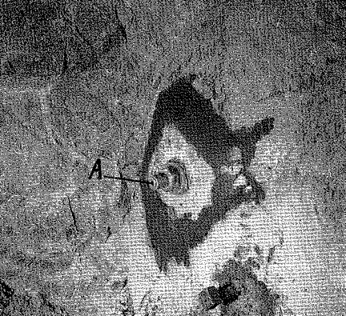
Fig. 15.—Measuring-type Rock Bolt.
“A” = stainless steel bush for insertion of gauge.
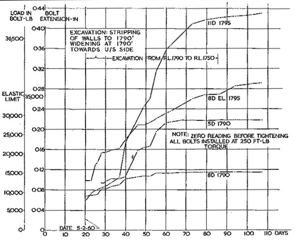
Bolts 14 ft. long modified in this way have been installed in the walls of Tumut 2 Power Station machine hall to investigate rock stability during excavation. Observations give the bolt tension at the time of installation, and subsequent changes in tension during excavation (Fig. 16).

Fig. 16.—Extensions of 14-ft. Measuring Bolts.
The figure shows the large extensions generally obtained during excavation, some of which were beyond the elastic limit of the bolts. An interpretation of the extension in terms of stress change and Young’s modulus suggests a very low modulus.
The method is simpler than the use of strain gauge load collars, which are expensive and liable to cable damage. It also has an advantage over rubber compression pads for bolt load measurements, which have a limited range of load. In addition, neither of these can be used with grouted bolts. The accuracy of measurement is better than 0.001 in. and is fully satisfactory for observation of changes during excavation.
10.—Acknowledgments
The work described was carried out under the supervision of Mr. T. K. Hogan, as part of the investigations of the Snowy Mountains Hydro-electric Authority. It is released by permission of the Authority.
The author is indebted to Mr. A. Hosking for contribution of the test results on the bolted rock aggregate.
The interpretation of the stresses by the photoelastic method was contributed by Mr. G. Worotnicki.
The views expressed are those of the author and not necessarily of the Authority.
Refences
1. Gicot, H. (1948)—Compressibility of Soil, Third Congress on Large Dams, Stockholm. Q9, R56.
2. Jones, V. and McHenry, D. (1948)—Foundation bearing Tests at Davis Dam. U.S.B.R. Struct. Lab. Rep. No. SP-18.
3. Habib, M.P. (1950)—Determination of the Elastic Modulus for Rocks in situ. Ann. Inst. Tech. Batim. Trav. Pub. Sols et Fondations No. 3, Sept., p. 27.
